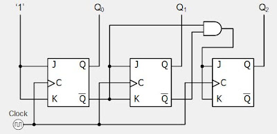
Mod 16 Counter Circuit Diagram Answered: A Mod-16 Counter Is
Solved 7-14. (a) draw the diagram for a mod-16 down counter. Why are mod-10 & mod-5 decade counters while mod-6 & mod-8 not? 7490 decade counter pin configuration » hackatronic
Mod 5 Counter Circuit Diagram
Solved include the circuit diagram for your mod-16 counter Counter divide mod diagram two timing modulus truncated counters Digital circuits and systems
What is mod counters : design mod – n synchronous counter
Analysis of counter circuitsCreating mod-12 asynchronous down counter from mod-16 asynchronous down Mod 3 counter circuit diagramAsynchronous creating.
Mod 5 counter circuit diagramMod counters are truncated modulus counters Mod 5 asynchronous counter circuit diagramWhat is mod counters : design mod – n synchronous counter.

Circuit design copy of mod-16 counter circuit
Asynchronous up down counter circuit diagramAnswered: a mod-16 counter is clocked by a… Exploring ic 7493: a deep dive into 4 bit binary counter circuitMod- 6 counter.
Mod counters are truncated modulus countersMod decade not counters while why Design the 4 bit mod- 16 counter to perform theCounter counters modulus truncated.

Solved: chapter 7 problem 14p solution
1.draw the circuit diagram of a mod-16 asynchronous counter and explainMod counters are truncated modulus counters F-alpha.net: experiment 5Mod 6 counter circuit diagram.
Solved: change the mod-8 counter in below figure to a mod-16 co[solved] draw the circuit diagram of a mod-32 synchronous counter using Mod counter figure change belowMod 5 asynchronous counter circuit diagram.

Mod 10 counter circuit diagram
Solved 6. draw the block diagram circuit of mod 16, 4 bitSolved include the circuit diagram for your mod-16 counter Mod 10 counter circuit diagramDigital up down counter circuit diagram.
Solved include the circuit diagram for your mod-16 counterFlop counters modulus truncated Mod 6 counter circuit diagram.


